MOUNTING / FASTENER / FIXTURE REVIEW
Review the complete donut load cell mounting stack.
Start with where compression enters and leaves the sensing body. The center bore, washers, support and electrical chain are one installation decision.
Download the engineering checklist (PDF) ↓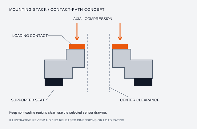
Separate loading, support and non-loading surfaces.
Some annular designs use distinct inner loading and outer support regions connected by an elastic section. Others have different contact geometry. Use the selected sensor drawing to locate the intended interfaces; do not assume the full top and bottom faces can be clamped indiscriminately.
A soft, oversized or misplaced washer can bridge a non-loading region. An unsupported seat can add bending. Review contact diameters, full support, washer stiffness and face condition before increasing preload.
Clear the shaft without losing contact area.
Specify the finished bore and tolerance relative to the actual shaft or fastener, its motion and alignment. Leave the required operating clearance while retaining enough supported annulus. A universal clearance value does not cover every bore, temperature or fixture.
Locating threads, a stud or dowel should control position without introducing an unintended torque or bypass force path. Include engagement, fastening method and handling orientation in the drawing review.
Use a repeatable installation and zero check.
- Inspect the seating faces and specified washers; remove contamination and confirm the contact regions.
- Assemble with the documented alignment and mounting method, keeping shaft side contact and cable strain clear.
- Connect the intended instrument and inspect unloaded zero before and after the mounting step.
- Apply the agreed controlled compression sequence within the approved operating range; compare output and zero return.
- Investigate unexpected zero shift, hysteresis or channel imbalance before using the assembly for production measurements.
Installation torque can create force much higher than an operator expects. Monitor force during tightening where appropriate and use the specific assembly procedure; the sensor's safe-overload value is not a working range.
Capture the engineering inputs before an RFQ.
1. Define the force
- Record working force, preload and credible peak separately, in lbf or kN.
- State compression direction, cycle rate, transient duration and required measurement resolution.
- Identify whether the reading represents one clamp point, one fastener or the complete machine.
2. Measure the installation
- Record actual center bore ID, OD, sensor height and complete washer stack in inches and mm.
- Include finished ID tolerance, shaft or fastener size, cable exit and connector clearance.
- Identify the intended loading and support annuli from the specific sensor drawing.
3. Review contact and mounting
- Check flat, parallel support and the specified washer material, hardness and contact diameters.
- Keep non-loading surfaces clear; a washer or fixture must not bridge the intended elastic gap.
- Control side contact, bending and installation torque; agree thread engagement and locating features.
4. Match the electrical chain
- Provide excitation, rated mV/V, input/output resistance and instrument input span.
- Record connector model, pin numbering view, polarity, shielding and cable length.
- Specify output type, required sample rate/bandwidth, zero/span procedure and shunt data if used.
5. Agree acceptance and procurement
- Specify force points, ascending/descending sequence, repeats and required uncertainty or traceability.
- Request the serial number, drawing revision, calibration record and applicable material/sealing evidence.
- Include original model/options, quantity, destination/postal code and required delivery date.
The HTML list and downloadable PDF use the same source checklist. Neither approves an installation, a safety function or a specific sensor/fixture combination.
Choose a calibration scope that matches the job.
A static force certificate and a high-speed peak measurement answer different questions. Include amplifier bandwidth, sampling, filtering and peak duration when evaluating press or fastener transients. Agree whether acceptance covers the bare sensor or the assembled measurement chain.
Record original model/options, quantity and destination alongside force and dimensions so the resulting drawing and quotation address the installed application.
Original manufacturer guidance on flat, parallel loading surfaces ↗