DLC-100 / IMPERIAL ENGINEERING SERIES
Smooth-Bore Compression Donut Load Cells
The standard donut type load cell for compression around a central shaft passage. Smooth center bores and raised loading rings suit axial preload, cylinder pushrods and die-ejector fixtures.
Configure DLC-100 & request quote ↗Drawing-led supply · one-piece modification inquiries · worldwide export quotation
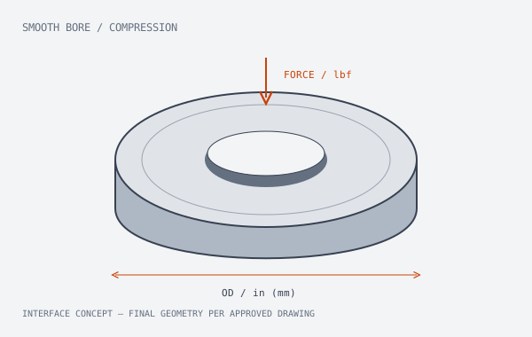
IMPERIAL-FIRST CONFIGURATION TABLE
50–10,000 lbf around your center bore
| Model (DLC-xxx) | Capacity (lbs / kN) | Center Bore ID (in / mm) | Outer Dia. OD (in / mm) | Height H (in / mm) | Lead Time |
|---|---|---|---|---|---|
| DLC-100 | 50–10,000 lbf0.222–44.482 kN | 1/8–2 in (3.175–50.8 mm), selected options | Per approved drawingSpecify maximum in / mm | Drawing-specific | 7-day machining optionConfirm configuration & dispatch |
Control contact stress, alignment and peak load
A bore that clears the shaft can still leave too little supported loading area. Confirm both annular contact surfaces and the assembled stack before setting preload.
Material & configuration evidence
17-4PH stainless steel; heat-treatment and hardness record available for the approved configuration.
DLC-100 configuration decisions
- Precision-ground annular loading surfaces help define where compression enters the sensor.
- Smooth-bore options keep a separate shaft or stud clear of the sensing body.
- Imperial dimensions and a defined mV/V interface support existing US-style fixtures.
Verify compression calibration in the intended fixture
Review bore and OD measurements, face parallelism, zero balance, excitation, rated sensitivity and ascending / descending compression readings.
Agree rated force, approved drawing revision, excitation, sensitivity, cable / connector pinout and acceptance points before releasing a sample. Request configuration-specific dimensional and calibration records rather than inferring them from a series name.
Review the force path and mV/V example →Where DLC-100 fits the assembly
- Die-ejector force measurement
- Bearing axial preload
- Pneumatic and hydraulic pushrod fixtures
Application examples define a selection direction. They do not establish medical, aerospace or safety-system approval.
DLC-100 bore, output and ordering questions
Is a 1/2 inch nominal bore always 0.500 inch clearance?
No. Nominal shaft or fastener size and finished clearance diameter are different values. Specify the required finished ID and tolerance on the installation drawing.
Can a DLC-100 replace a Honeywell or THC sensor?
It is a comparison starting point. Send the original complete model and options, mechanical drawing, wiring and calibration data. Matching capacity alone does not establish interchangeability.
FAST-TRACK ENGINEERING RFQ
Send DLC-100 force, bore and mounting requirements.
Choose the load-bearing washers, paired interface or bottom-thread modification below. Your configuration and selected add-ons travel together to engineering.