DLC-SM / IMPERIAL ENGINEERING SERIES
Stud-Mount & Threaded Donut Load Cells
A donut load cell stud mount configuration keeps the sensor located in vertical, inverted or vibrating fixtures. Choose bottom mounting threads, an external stud or a threaded center bore as distinct interfaces.
Configure DLC-SM & request quote ↗Drawing-led supply · one-piece modification inquiries · worldwide export quotation
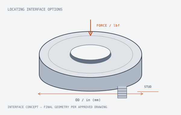
Keep locating torque out of the measured force
Positioning threads do not automatically form the calibrated force path. Installation torque, bending and a bottom stud can load the body differently from a flat compression seat.
Material & configuration evidence
17-4PH stainless steel sensing-body option; thread engagement, mounting hardware and loading surfaces are defined together.
DLC-SM configuration decisions
- UNF options include #10-32, 1/4-28, 3/8-24 and 1/2-20, with M6–M24 metric options for review.
- Bottom location features can prevent a sensor from slipping out during fixture handling.
- One-piece machined modification inquiries are accepted without a mold-tooling charge; machining and special engineering costs are quoted separately.
IMPERIAL-FIRST CONFIGURATION TABLE
UNF / metric locating interfaces and axial force
| Model (DLC-xxx) | Capacity (lbs / kN) | Center Bore ID (in / mm) | Outer Dia. OD (in / mm) | Height H (in / mm) | Lead Time |
|---|---|---|---|---|---|
| DLC-SM | 100–20,000 lbf0.445–88.964 kN | Thread or clearance ID per drawing | Per approved drawingSpecify maximum in / mm | Drawing-specific | 7-day machining optionConfirm configuration & dispatch |
Verify compression calibration in the intended fixture
Agree thread designation, engagement, concentricity, fastener torque limits, loading contact and the calibration fixture. Check zero shift after assembly.
Agree rated force, approved drawing revision, excitation, sensitivity, cable / connector pinout and acceptance points before releasing a sample. Request configuration-specific dimensional and calibration records rather than inferring them from a series name.
Review the force path and mV/V example →Where DLC-SM fits the assembly
- Vertical and inverted automation fixtures
- Anti-rotation fixture location
- Shaft-end axial force assemblies
Application examples define a selection direction. They do not establish medical, aerospace or safety-system approval.
DLC-SM bore, output and ordering questions
Which donut load cell threads should I specify?
State whether the thread is in the center bore, on an external stud, or in bottom mounting holes. Then provide the complete size, pitch, engagement length and orientation. A nominal thread diameter is not the free bore clearance.
Are bottom mounting threads the same as a stud mount?
No. Bottom tapped holes receive separate fasteners; an external stud is part of the mounting interface. Their locating and load-transfer behavior must be reviewed against the fixture drawing.
FAST-TRACK ENGINEERING RFQ
Send DLC-SM force, bore and mounting requirements.
Choose the load-bearing washers, paired interface or bottom-thread modification below. Your configuration and selected add-ons travel together to engineering.