CUSTOM BORE & OEM / DLC CONFIGURATION REVIEW
Custom donut load cell design around your fixture.
Start with the dimensions that cannot change: center bore ID, outside diameter, installed height and the location of the loaded annulus. Then match the force range, mounting and electrical interface.
Request an engineering quote ↗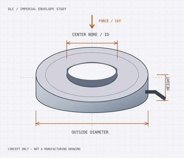
1.5, 2 and 3 inch ID are the beginning of the review.
A nonstandard center bore changes the remaining sensing body and available contact area. Specify actual clearance and tolerance, rather than only the shaft nominal size.
Inches first, millimeters beside them
- 1.5 in = 38.1 mm center-bore review input
- 2.0 in = 50.8 mm center-bore review input
- 3.0 in = 76.2 mm center-bore review input
- 4.0 in = 101.6 mm center-bore review input
Confirm OD, height, corner radii, cable gland clearance and loading washers together. Missing dimensions are held for drawing review.
Choose the locating feature before cutting threads.
Bottom tapped holes, external studs and an internally threaded center bore serve different assemblies. Include the complete UNF or metric designation, engagement length, fastener torque and orientation. Do not assume a locating screw can carry the calibrated axial force.
17-4PH, signal and acceptance requirements
The supplied design direction uses 17-4PH stainless steel, with HRC 43–45 vacuum heat treatment specified where applicable. Include any required material / hardness record, laser-welded environmental sealing and immersion conditions in the RFQ.
Define excitation, rated mV/V output, bridge resistance, cable, pinout and calibration points. One-piece machined modifications are accepted without a mold-tooling charge; custom machining, engineering work and the selected scope are quoted.